
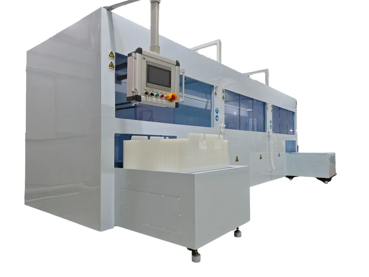
| 1.1 Equipment Overview
The main function is to clean the components, and this equipment has a good cleaning process; Basic parameter table of equipment |
 |
| Equipment name | Fully automatic cleaning machine | |
| Equipment number | NTYJ-QZDQX24-03 | |
| quantity | 1 unit | |
| Equipment size | 6400mm(L)×2700mm(W)×2200mm(H) | |
| Cleaning product size | L700mm*W700mm*H200mm | |
| Loading and unloading materials | hand movement | |
| process control | PLC control | |
| TOUCH SCREEN CONTROLLER | ||
| Liquid inlet control | Manual liquid preparation | |
| DIRECTION | Machine direction | Forward, forward, out |
| Mechanical arm bearing | Capacity | Max.50Kg/time |
| Quantity of workpieces | Single basket/time | |
| Dual protection for dry burning hardware and software | not have | |
| Liquid level protection function | have | |
| Temperature protection function | not have | |
| Leakage detection function | have | |
| Time setting | 0-12 hours can be set (depending on the actual process time) | |
| Capacity design | Two shift system (note: working 24H/day, 360 days/year) | |
|
Equipment stability |
UPTIME: UPTIME ≥ 98% (1- (fault time+PM time)/total time) | |
| MTTR: MTTR ≤ 4h (MTTR=total repair time/total number of failures) | ||
| MTBE: MTBE ≥ 450h (MTBF=total operating time/total number of failures) | ||
| Equipment operating temperature range | 20-25°C | |
| relative humidity | <70% | |
1.2 Equipment Features
| standard | The design, selection, manufacturing, inspection, and testing of this equipment are carried out in accordance with relevant national and semiconductor industry standards (SEMI-S2-93), standardized and guaranteed by the ISO9001 quality management system, except as otherwise specified in the contract or technical documents. The purchased accessories shall comply with the corresponding national standards, industry standards, specifications, and enterprise standards |
| The equipment includes | Equipment body, electrical control part, chemical process tank, etc; And provide interfaces that are compatible with the factory’s power supply, gas supply, water supply, wastewater discharge, exhaust system, etc |
| main body | The main body of the equipment is made of domestic porcelain white 10mm PP board, which is sturdy and durable, with double-layer leak proof, |
| Skeleton | SUS304+PP domestic porcelain whiteboard combination to prevent rusting of the shell |
| safety door | Install transparent PVC doors that move left and right to separate and protect personnel safety, |
| Process tank | Modular design, with the corrosion tank and pure water flushing tank placed in a unified leak proof chassis. The chassis is processed using full welding technology to eliminate the risk of machine leakage |
| pipe system | Located at the bottom of the equipment, all process tanks, pipelines, and valve parts are clearly labeled; PFA pipes are used for the liquid medicine pipeline, PFA pipes are used for the pure water pipeline, and the chemical corrosion tank waste liquid and flushing wastewater are discharged through dedicated pipelines |
| electrical protection | The electrical control, gas path control, and process tank control sections are located in a separate electrical control area at the rear of the equipment. The electrical components are adequately protected against acid mist corrosion to ensure stable and reliable equipment performance and operation; |
| Machine support legs | There are pulley devices and fixing devices with anti-corrosion seats, and they have height adjustment and locking functions |
| security guarantee | Complete alarm and protection design, hardware or software interlocking for exhaust pressure, liquid level, and drainage, intuitive operation interface, clear information prompts, ensuring production, process control, and safety. The three color warning light is placed prominently above the machine |
2. Process flow and process details
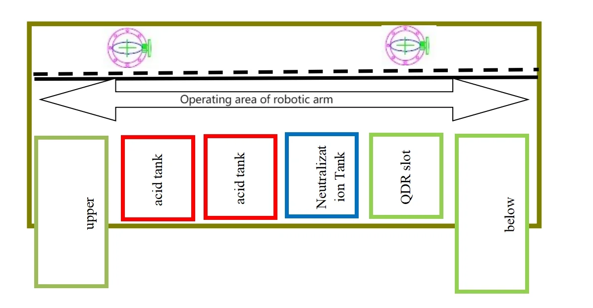
2.1 Process flow:
1 # Pickling -2 # Pickling -3 # Neutralization -4 # Cleaning
2.2 Outline structure diagram: refer to the drawing;
2.3 The table layout is as follows
2.4 Process parameters for each slot:
| production processes | Auxiliary functions | Time (S) | Temperature (℃) | material | Slot cover | heater | convulsions | |
| 1 | acid pickling | Soak and bubble | 0-9999 | RT | NPP | have | not have | have |
| 2 | acid pickling | Soak and bubble | 0-9999 | RT | NPP | have | not have | have |
| 3 | neutralization | soak | 0-9999 | RT | NPP | have | not have | have |
| 4 | QDR | Water inlet spray
Overflow bubbling tympanic bulla |
0-9999 | RT | NPP | not have | not have | have |
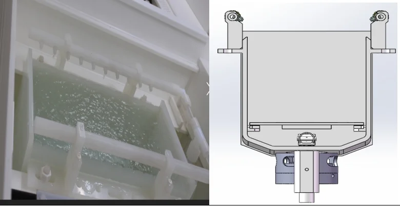
2.5 Pickling tank (1 # 2 #)
| medium | acid liquor |
| Work energy | Soak and bubble |
| Tank material | Imported NPP from Germany |
| Tank size | L800mm*W800mm*H400mm |
| Usage temperature | RT |
| Liquid inlet method | Manual liquid inlet |
| water feeding pattern | Automatic water intake |
| Bubble method | The PFA tube at the bottom of the tank is evenly bubbling |
| Liquid level method | Connecting pipe liquid level |
| Drainage method | Automatic pump discharges into the recycling bin |
| Slot cover method | Manual NPP slot cover |
2.6 Neutralization tank (3 #)
| medium | lye |
| Work energy | Soak and neutralize |
| Tank material | Imported NPP from Germany |
| Tank size | L800mm*W800mm*H400mm |
| Usage temperature | RT |
| Liquid inlet method | Manual liquid inlet |
| water feeding pattern | Automatic water intake |
| Liquid level method | Connecting pipe liquid level |
| Drainage method | Automatic pump discharges into the recycling bin |
| Slot cover method | Manual NPP slot cover |
2.7 QDR slot
| medium | DIW |
| Work energy | Spray water injection overflow bubble quick discharge |
| Tank material | Imported 10mm NPP board from Germany |
| Tank size | L800mm*W800mm*H400mm |
| Usage temperature | RT |
| Bubble method | PFA pipes are evenly distributed at the bottom, and the upper part of the bubble tube is equipped with a perforated plate |
| Spray method | Spray pipes are distributed on both sides of the upper part of the tank, with adjustable pressure and angle |
| Liquid inlet method | Automatic water inlet spray water injection time ≤ 10s |
| Drainage method | Fast emission time ≤ 5s |
|
technological process |
Step 1: Spray open the quick release and open it simultaneously
Step 2: Inject water, turn on the spray, turn on the bubble, turn on the bubble Step 3: After the water is full, overflow and open to soak The time for the above steps is in seconds and can be set. The batch can also be set |
|
Tank body diagram |
 |
3. Electrical components
3.1 Electrical box section
| Electrical box section | Equipped with an independent power distribution area, |
| The equipment is equipped with a ventilation system to ensure air circulation inside the electrical box and has good heat dissipation function | |
| All electrical control systems are equipped with leakage protectors, reliable grounding devices, and emergency shutdown and alarm systems; |
3.2 Control section
| controller | The equipment is divided into automatic and manual parts during use. No other operations can be performed during automatic operation. In case of any problems, please press the emergency stop device. When the emergency stop is pressed, all work will be suspended. It is strictly prohibited to perform manual operations during automatic operation; |
| Human computer interface: adopting professional and advanced graphical user interface, easy to operate and master, capable of completing trajectory editing and modification according to needs. | |
| Basic functions: password verification login, security protection door protection, alarm and other security functions, storage functions such as process prescription, operation and maintenance records, etc | |
| Tank control: Each tank has a corresponding separate control panel on the upper part of the front plate. The liquid tank has separate function buttons for temperature display, liquid level display, and status display. The QDR tank has separate start/stop buttons for each tank, as well as separate buttons for spraying, water inlet, bubbling, drainage, and other means; | |
| Warning light, buzzer, emergency stop | |
| Touch screen function: There is a manual operation button for the device, and real-time monitoring of the equipment is completed according to the pipeline diagram setting screen. Various functions of each tank are monitored, including temperature, liquid level, tank cover status, mechanical arm in place status, pump and valve start and stop, alarm display, and alarm recording. | |
| Interface settings: various parameter settings, interfaces for management personnel, process personnel, operators, etc. | |
| All chemical tanks are equipped with capacitive level sensors to prevent pump idling. Capacitive level gauges are added to the heating tanks to prevent dry burning of the heaters; | |
| The robotic arm automatically returns to the origin within a fixed time, eliminating mechanical and electrical errors; | |
| Equipment power-off protection function, protecting against program failures caused by unexpected power outages; | |
| The equipment has an automatic alarm information recording system |
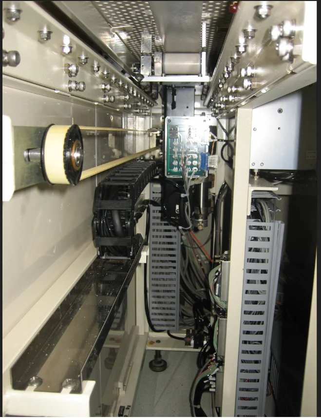
4. Robot arm system
4.1 Lateral translation of robotic arm
| 1 | electrical machinery | servo motor |
| 2 | power | 750W+reducer+brake |
| 3 | SPEED CONTROL | Stable start of translation, acceleration translation, deceleration stop |
| 4 | linear guide rail | Linear bearing guide rail |
| 5 | Rack and pinion | customized |
|
6 |
Walking pictures |
 |
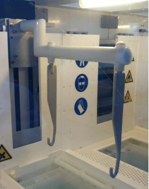
4.2 Mechanical arm up and down hooking
| 1 | electrical machinery | servo motor |
| 2 | power | 750W+reducer+brake |
| 3 | SPEED CONTROL | Stable start of translation, acceleration translation, deceleration stop |
| 4 | linear guide rail | Linear bearing guide rail |
| 5 | Ball screw | Upper Silver Linear Precision Guidance Mechanism |
| 6 | load | 50Kg |
|
7 |
gripper mechanism |
 |
5. Equipment utility engineering conditions
5.1 Electric Power Conditions
| voltage | 380V |
| frequency | 50Hz |
| Number of phases | Three-phase five-wire system |
| power | 8KW |
| loop | DC24V |
5.2 Gas dynamic conditions of liquid medicine
| medium | temperature | material | Pressure kgf/cm2 | nature | caliber | Connection method |
| liquid | ||||||
| pure water | RT | PFA | 2.5-3 | ≥ 18 MB | 3/4*6 | Direct insertion |
| gas | ||||||
| CDA | RT | PU tube | 5-6 | no oil | Φ10*2 | Direct insertion |
| N2 | RT | PU tube | 4-5 | Purity ≥ 99.99% | Φ10*3 | Direct insertion |
| emission | ||||||
| waste water | RT | PP | — | — | DN32*1 | slipknot |
| Exhaust emissions | ||||||
| gas | RT | PP | — | — | Φ200*2 | flange |
6. List of Main Materials for Equipment
| Serial Number | name | quantity | Specification and model | Supplier manufacturer |
| 1 | skeleton | 1 | 50 * 50 (3mm thick) | domestic |
| 2 | casing | 1 | Porcelain white PP10mm | domestic |
| 3 | Transparent observation doors and windows | 2 | 5mm | South Asia |
| 4 | Foot accessories | 4 | M22 | domestic |
| 5 | temperature sensor | 1 | E5CZ | Omron Japan |
| 6 | Liquid level sensor | 3 | Omron Japan | |
| 7 | solenoid valve | 3 | 2-position 3-way/straight through | SMC |
| 8 | Pipelines and valves | 10 | DN25/DN40 PP/PFA | GF/CKD |
| 9 | PLC controlling sYstem | 1 | Wistron | |
| 10 | Touch Screen | 1 | 7” | Wistron |
| 11 | Air switch, contactor | 6 | schneider | |
| 12 | temperature control | 6 | Omron | |
| 13 | relay | 5 | schneider |
7. Manufacturing cycle
50 working days after the prepayment of the effective subject matter of the contract is received;
We guarantee that we will not outsource the production and processing of all equipment for your company;
8. Equipment delivery inspection and transportation
8.1 Acceptance standards and acceptance criteria
Table 7-1 Acceptance Specifications
| Serial Number | project subject to check and delivery | Testing parameters or requirements | test method | notes |
| 1 | appearance | Clean surface and clear labeling | visualization | |
| 2 | External dimensions | According to the contract requirements | taping | |
| 3 | Tank size | According to the contract requirements | taping | |
| 4 | maximum temperature | According to the contract requirements | Using a thermometer for measurement | |
| 5 | minimum temperature | According to the contract requirements | Using a thermometer for measurement | |
| 6 | precision | According to the contract requirements | Using a thermometer for measurement | |
| 7 | control mode | visualization | visualization | |
| 8 | power supply | Embedded flow table | ||
| 9 | power | Embedded flow table | ||
| 10 | Security testing | 1500V communication, no breakdown for 1 minute | According to GB4793.1-1999
Test according to the voltage withstand tester |
pressure resistance |
| After stabilizing at 500V DC for 10 seconds, the insulation resistance value should be above 2M ohms | Insulation resistance tester testing |
Table 8-2 Acceptance Criteria
| Serial Number | Testing items | describe |
| 1 | appearance | The product shell has no obvious deformation, cracks, bending or other serious damage, and the fastening parts are not loose, firm and reliable. If one of them is unqualified, it is allowed not to be accepted |
| 2 | performance index | Meet design and specification requirements |
| 3 | other | Execute according to the contents listed in this Technical Agreement |
9. Equipment installation and debugging
9.1 Installation, Installation, and Debugging
After the equipment is inspected and approved by Party B and notified to Party A, the responsibilities of each party are defined as follows
Job Responsibilities of Party B
Equipment unboxing;
Install the equipment in place according to the requirements of the factory layout plan;
Assembly and installation of equipment;
Under the guarantee conditions provided by Party A, Party B shall complete the installation according to the schedule and ensure the quality;
Equipment debugging and acceptance work
The first party is responsible for the following tasks
Place the power supply and standard air source in the installation position of the equipment and connect them;
The second party shall provide necessary assistance to the first party during the installation, debugging, and acceptance process
Complete positioning of the machine within 24 hours upon arrival; Complete secondary configuration within one week
9.2 Equipment acceptance
According to the quality assurance system, this acceptance standard is specially formulated as the basis for inspecting and accepting the equipment (including all contents of the contract) undertaken by Party B.
Design control: Based on the production outline proposed by Party A, Party B shall make reasonable designs in accordance with industry standards, and continuously optimize the scheme design during the communication process with Party A. For the structure of the equipment’s wiring, transmission, power, temperature control and other parts, a margin must be left in the selection to ensure long-term safe, reliable and stable operation, providing the most basic conditions for Party A to ensure product quality.
Manufacturing process control: The process of manufacturing equipment by Party B shall undergo strict inspection and experimentation, and any non-conforming products shall not proceed to the next process.
Inspection and acceptance: During the equipment manufacturing process and after the formation of finished components, strict inspection and testing must be carried out, and unqualified products are not allowed to enter the next process;
Handling, storage, packaging, protection, and delivery: Party B shall take measures to ensure product quality, and this protection shall continue until the delivery destination is installed, debugged, and delivered to Party A for use;
Installation and commissioning: Party B shall install and commission the equipment in accordance with industry regulations. Under the guarantee conditions provided by Party A, Party B shall complete the installation and commissioning work according to the schedule to ensure quality.
Personnel training: During the trial production process, Party B is responsible for providing training to Party A’s engineering and technical personnel on production line operation, maintenance, upkeep, and repair, as well as providing standardized training materials, circuit diagrams, and a complete list of spare parts.
9.3 Final acceptance
Acceptance of the appearance of the system: This equipment is a brand new and complete production device, as indicated in the signed specification sheet.
Equipment stability acceptance: Uptime ≥ 98%.
The equipment has been confirmed to meet production requirements and has been running continuously for 3 months. During this period, the equipment has no abnormalities and meets the technical specifications. The acceptance process will be followed.
10. Service Guarantee
10.1 Equipment Quality Assurance
The second party guarantees the equipment for one year after the start of debugging. Kunshan Xinruiwei Company is responsible for on-site installation of the system and provides free technical support and services for one year from the date of acceptance;
The second party guarantees that the quality, specifications, brand, and place of origin of all materials and components shall comply with the contract
The process layout, equipment arrangement, general assembly drawing, and technical documents need to be confirmed and signed by both parties before they can be put into construction.
The second party shall provide the first party with formal drawings of various equipment for technical certification after the contract is signed. If there are any technical changes during the manufacturing process, they must be confirmed by both parties before they can take effect; The second party shall strictly follow the drawings, rapid documents, and relevant regulations during the manufacturing and construction process, and conduct more comprehensive technical quality supervision and control.
During the manufacturing process of Party B, Party A shall conduct intermediate inspections on the manufacturing quality. Before the equipment leaves the factory, Party A shall conduct a pre acceptance inspection at Party B’s factory.
The equipment provided by Party B must operate normally, be safe and reliable, have a beautiful appearance, and have harmonious color tones;
During the quality assurance period, the supplier provides free warranty for the system. If the purchaser requests maintenance, the manufacturer should respond within 2 hours and provide a solution within 4 hours. If a solution can be quickly resolved, personnel will be dispatched to the site within 24 hours and the repair will be completed within 6 hours; After the warranty period ends, the manufacturer still provides lifelong maintenance, upkeep, modification, system upgrades and other services for the equipment. The material costs, labor costs and other expenses shall be borne by the purchaser after confirmation. For the maintenance needs of the demand side, the manufacturer should still complete them according to the time requirements within the warranty period.
10.2 Quality Requirements and Safety
Each device should run smoothly, without crawling, impact, shaking, leakage or other adverse phenomena. The heating system and ultrasonic system should be safe and reliable, and the exhaust system should be designed and manufactured reasonably;
The design and installation of all electrical appliances, distribution boxes, and their control boxes shall comply with the safety standards of national electrical technology, and all mechanical installations shall meet the accuracy levels required by relevant national regulations.
Water, air, and air connections are not allowed to have any air, air, or water leakage.
The connections of the equipment should be straight, and the metal surface should be sprayed flat, smooth, without paint leakage, and have uniform color.
Equipment, heating devices, or other power equipment should have good overload protection and emergency braking protection devices.
Related important components require size reports, quality reports, inspection reports, etc.
10.3 Technical Services for Training
10.3.1 Technical Services
Free technical support and services are provided for one year from the date of acceptance.
During the trial operation of the equipment, Party B shall be responsible for training the mechanical and electrical maintenance personnel designated by Party A, including equipment operation and maintenance, analysis and handling of common faults.
10.3.2 Training
| Serial Number | content | Participants in the training | Start Time | time | notes |
| 1 | Equipment principle and structure training | Electrical and mechanical engineers responsible for equipment | After the equipment debugging is completed | 1 day | Provide equipment manuals and training materials |
| 2 | Training on equipment operation, emergency response, equipment maintenance, etc | Electrical and mechanical engineers responsible for equipment | After the equipment debugging is completed | 1 day | Provide equipment manuals and training materials |
| 3 | Equipment principle and structure training | Equipment users | After the equipment debugging is completed | 1 day | Provide equipment manuals and training materials |
11. Explanatory document
11.1 Equipment Technical Data
System Operation Manual
Electrical control circuit diagram (PLC circuit diagram, electrical wiring diagram).
11.2 Equipment accessories and spare parts
Provide a list of spare parts required for the normal use and maintenance of the equipment;
Provide a list of vulnerable parts.
12. Equipment safety
Equipment operation should be strictly carried out in accordance with the operating instructions, and operation and maintenance personnel should receive specialized training;
The parts that may cause harm to the human body are clearly marked with warning signs on the equipment;
The professional operation section has clear warning signs on the equipment;
There are clear operating steps for special operations.