
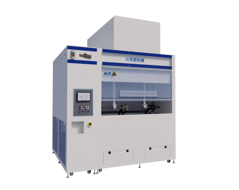
| 1.1 Equipment Overview
The main function is to clean quartz tubes with an outer diameter of 290mm and a length of 2500mm Basic parameter table of equipment |
 |
| Equipment name | Furnace tube cleaning machine |
| Equipment number | ASSH-QF-241018 |
| quantity | 1 unit |
| Equipment size | 3500mm(L)×2500mm(W)×2200mm(H) |
| Cleaning product size | 2500mm (L) X290mm (D)/Single (8-inch furnace tube) |
| Time setting | 0-12 hours can be set (depending on the actual process time) |
| Equipment form | Indoor placement type |
| Capacity design | Two shift system (note: working 24H/day, 360 days/year) |
|
Equipment stability |
UPTIME: UPTIME ≥ 98% (1- (fault time+PM time)/total time) |
| MTTR: MTTR ≤ 4h (MTTR=total repair time/total number of failures) | |
| MTBE: MTBE ≥ 450h (MTBF=total operating time/total number of failures) | |
| Equipment operating temperature range | 20-25°C |
| relative humidity | <70% |
1.2 Equipment Features
| standard | The design, selection, manufacturing, inspection, and testing of this equipment are carried out in accordance with relevant national and semiconductor industry standards (SEMI-S2-93), standardized and guaranteed by the ISO9001 quality management system, except as otherwise specified in the contract or technical documents. The purchased accessories shall comply with the corresponding national standards, industry standards, specifications, and enterprise standards |
| The equipment includes | Equipment body, electrical control part, chemical process tank, etc; And provide interfaces that are compatible with the factory’s power supply, gas supply, water supply, wastewater discharge, exhaust system, etc |
| main body | The overall design of the equipment is integrated, and the main body of the equipment is made of German imported SIMONA porcelain white 10mm PP board, which is sturdy, durable, and double-layer leak proof, |
| Skeleton | SUS304+porcelain white German imported SIMONA PP board combination to prevent rusting of the shell |
| safety door | Install high transparency PVC upper and lower cylinder safety doors on the equipment, which are divided into two safety doors on the left and right to separate and protect personnel safety; Equipment sealing strip at the edge |
| surface | The height is about 950mm, and the platform panel is evenly distributed with circular holes of Φ 10mm. The structural design fully considers long-term operation in acid corrosion environment |
| Process tank | Modular design, with the corrosion tank and pure water flushing tank placed in a unified leak proof chassis. The chassis is processed using full welding technology to eliminate the risk of machine leakage |
| pipe system | Located at the bottom of the equipment, all process tanks, pipelines, and valve parts are clearly labeled; The medication pipeline uses PILLAR PFA pipes, the pure water pipeline uses GF PVDF pipes, and the chemical corrosion tank waste liquid and flushing wastewater are discharged through dedicated pipelines |
| electrical protection | The electrical control, gas path control, and process tank control parts are located in separate electrical control cabinets at the rear of the equipment. The electrical components are adequately protected against acid mist corrosion to ensure stable and reliable equipment performance and operation; All electrical and wiring that may come into contact with acid mist are treated with PFA anti-corrosion isolation, and the electrical cabinet CDA/N2 is inflated to protect the electrical control components inside |
| Work lighting | The acid resistant and alkali resistant LED lighting fixtures above are replaceable at 220V and 40W, with LED lighting parameters ranging from 4000-5500K |
| Water vapor gun | The front of the machine is equipped with two Parker PP pure water guns and two PP nitrogen air guns, which are placed on both sides. The water guns are designed to drip live water, making it convenient for operators to manually clean the tank or workpiece |
| Machine support legs | There are pulley devices and fixing devices with anti-corrosion seats, and they have height adjustment and locking functions |
| security guarantee | Complete alarm and protection design, hardware or software interlocking for exhaust pressure, liquid level, and drainage, intuitive operation interface, clear information prompts, ensuring production, process control, and safety. The three color warning light is placed prominently above the machine |
2. Process flow and process details
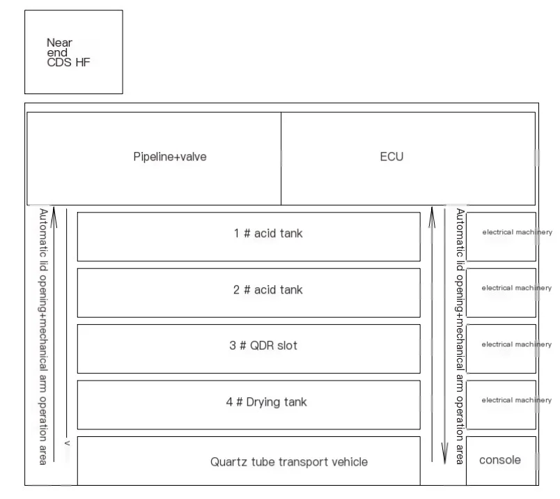
2.1 Process flow:
1 # Acid Bubble -2 # Acid Bubble -3 # Water Cleaning -4 # Drying
2.2 The table layout is as follows
2.3 Process parameters for each slot:
| production processes | Auxiliary functions | Time (S) | Temperature (℃) | material | Slot cover | convulsions | |
| 1 | Quartz tube transport vehicle | Loading and unloading transportation | 0-9999 | RT | NPP | not have | not have |
| 1 | acid tank | Soaking, bubbling, rotating | 0-9999 | RT | PVDF | automatic | have |
| 2 | acid tank | Soaking, bubbling, rotating | 0-9999 | RT | PVDF | automatic | have |
| 3 | QDR slot | Spray water injection
Overflow bubble rotation |
0-9999 | RT | NPP | automatic | have |
| 4 | Drying tank | Heating, drying, and rotating | 0-9999 | RT-80°C±3°C | SUS316L | automatic | have |
2.4 Quartz Tube Transport Vehicle
| Work energy | Loading, unloading, and transportation |
| Tank material | Imported SIMONA 10mm NPP board from Germany |
| Tank size | L2600 * W400 * 400mm (effective size) |
| Transportation method | Manual handling |
| Connection method | Place sensors with limited positions at both ends,
Check whether the transport vehicle is placed in place, with magnetic suction at the rear end to fix the position of the transport vehicle |
2.5 Acid tank (1 # 2 #)
| medium | HF |
| Work energy | Soaking, bubbling, rotating |
| Tank material | Imported SIMONA 10mm PVDF board from Germany |
| Tank size | L2600 * W400 * 400mm (effective size) |
| Usage temperature | RT |
| Bubble method | PFA pipes are evenly distributed at the bottom |
| Liquid level method | Connecting pipe liquid level |
| Liquid inlet method | Near end CDS automatic liquid inlet, supply pump adopts diaphragm pump |
| Fluid replacement method | Near end CDS automatic fluid replenishment |
| water feeding pattern | Automatic water intake |
| Hydration method | Automatic water replenishment of pipeline valves |
| Mutual fighting function | When the cleaning frequency of HF tank 1 # and HF tank 2 # reaches the upper limit and needs to be drained,
1 # HF tank is directly discharged, 2 # HF tank is discharged into 1 # HF tank, and 2 # HF tank is refilled with new solution |
| Tilt angle | The height difference of the rollers on both sides is 20-30mm, and the quartz tube tilts at a small angle |
| Rotation method | Drive rotation (rolling) groove device: corrosion-resistant PVDF active/passive shafts (adjustable) are installed on both sides of the groove bottom, and corrosion-resistant (scratch resistant quartz tube outer wall, prevent quartz tube slipping) O-rings are installed on the bearings |
| rotator | Drive rotation (rolling) device outside the groove: A closed motor drives the acid and alkali resistant gear outside the groove, which drives the driving wheel inside the groove to rotate the quartz tube through a chain made of acid and alkali resistant material, preventing corrosion. The speed is 5-10 revolutions per minute (adjustable) |
| Drainage method | Gravity discharge to buffer tank |
| Cache method | There is a cache slot installed at the bottom of the device, and a liquid level sensor is installed in the cache slot
The buffer tank liquid is pumped into the working operation through a diaphragm pump |
| Slot cover | Automatic PVDF tank cover |
2.6 QDR slot (3 #)
| medium | DIW |
| Work energy | Spray water injection overflow bubbling rapid discharge rotation |
| Tank material | Imported SIMONA 10mm NPP board from Germany |
| Tank size | L2600 * W400 * 400 mm (effective size) |
| Usage temperature | RT |
| Bubble method | PFA pipes are evenly distributed at the bottom, and the upper part of the bubble tube is equipped with a perforated plate |
| Tilt angle | The height difference of the rollers on both sides is 20-30mm, and the quartz tube tilts at a small angle |
| Rotation method | Drive rotation (rolling) groove device: The bottom of the groove is equipped with corrosion-resistant PVDF stainless steel active/passive shafts (adjustable) on both sides, and the bearings are equipped with corrosion-resistant (scratch resistant quartz tube outer wall, prevent quartz tube slipping) O-rings |
| rotator | Drive rotation (rolling) device outside the groove: A closed motor drives the acid and alkali resistant gear outside the groove, which drives the driving wheel inside the groove to rotate the quartz tube through a chain made of acid and alkali resistant material, preventing corrosion. The speed is 5-10 revolutions per minute (adjustable) |
| Liquid inlet method | Automatic water inlet spray water injection |
| Drainage method | Rapid emission |
|
technological process |
Step 1: Spray open the quick release and simultaneously open the rotating opening
Step 2: Inject water, turn on the spray, turn on the bubble, turn on the rotation, and open it Step 3: After the water is full, overflow and bubble open to complete the soaking process The time for the above steps is in seconds and can be set. The batch can also be set |
2.7 Drying Tank (4 #)
| medium | nitrogen |
| Work energy | Heat and blow dry |
| Tank material | Imported SUS316L stainless steel with a thickness of 2mm |
| Tank size | L2600 * W400 * 400 mm (effective size) |
| Usage temperature | RT-80°C±3°C |
| Heating method | SUS online heater heating+infrared heating |
| Temperature control method | PID control method |
| Over Temperature Protection | Cut off the heating power supply when the set temperature exceeds 5 ° C |
| Air Intake method | Automatic intake |
| Blowing method | Blow the outer wall of the quartz tube with nitrogen nozzles on both sides, and blow the inner wall of the quartz tube with nozzles on the end face of the quartz tube |
| Tilt angle | The height difference of the rollers on both sides is 20-30mm, and the quartz tube tilts at a small angle |
| Rotation method | Drive rotation (rolling) groove device: corrosion-resistant PVDF active/passive shafts (adjustable) are installed on both sides of the groove bottom, and corrosion-resistant (scratch resistant quartz tube outer wall, prevent quartz tube slipping) O-rings are installed on the bearings |
| rotator | Drive rotation (rolling) device outside the groove: A closed motor drives the acid and alkali resistant gear outside the groove, which drives the driving wheel inside the groove to rotate the quartz tube through a chain made of acid and alkali resistant material, preventing corrosion. The speed is 5-10 revolutions per minute (adjustable) |
| Drainage method | gravity discharge |
| Slot cover | Automatic SUS316L slot cover |
3. Lifting robotic arm
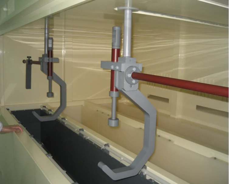
3.1. Introduction to Main Functions
| Mechanical arm bearing | Capacity | Max.60Kg/time |
| Number of furnace tubes | 1 piece/time | |
| Function Description | Number of robotic arms | 1 |
| Rotating flower basket device | have | |
| Flower basket lifting device | have | |
| Arm material | PVC | |
| The pneumatic valve is separated from the slot cover cylinder air circuit | not have | |
| Detection of working liquid level in each tank | have | |
| motor control | Mitsubishi/Panasonic | |
| Position protection function | Servo parameter protection+position sensor protection | |
| Management protection function | Position sensor protection | |
| Liquid level protection function | have | |
| Temperature protection function | have | |
| Leakage detection function | have |
4. Electrical components
4.1 Electrical Cabinet Section
| Electrical cabinet section | The equipment is equipped with an independent power distribution area, which is equipped with temperature control alarms. The circuit is divided into functional blocks, with strong and weak electricity divided for easy maintenance; |
| The equipment is equipped with a ventilation system to ensure air circulation inside the electrical cabinet and has good heat dissipation function; | |
| All electrical control systems are equipped with leakage protectors, reliable grounding devices, and emergency shutdown and alarm systems; |
4.2 Control section
| controller | The equipment is divided into automatic and manual parts during use. No other operations are allowed during automatic operation. In case of any problems, please press the emergency stop device. Manual operation during automatic operation is strictly prohibited; Manual operation is strictly prohibited when heating the equipment |
| Human computer interface: adopting professional and advanced graphical user interface, easy to operate and master, capable of completing trajectory editing and modification according to needs. | |
| Basic functions: password verification login, security protection door protection, alarm and other security functions, storage functions such as process prescription, operation and maintenance records, etc | |
| Warning light, buzzer, emergency stop | |
| The upper computer adopts Siemens and controls the functions of the host screen: there is a manual operation button for the equipment, and real-time monitoring of the equipment is completed according to the pipeline diagram setting screen. Various functions of each tank are monitored, including temperature, liquid level, tank cover status, mechanical arm in place status, pump and valve start and stop, alarm display, and alarm recording. | |
| Interface settings: various parameter settings, interfaces for management personnel, process personnel, operators, etc. | |
| All chemical tanks are equipped with capacitive level sensors to prevent pump idling. Capacitive level gauges are added to the heating tanks to prevent dry burning of the heaters; | |
| The equipment has an automatic alarm information recording system | |
| When shielded separately, manual operation is possible | |
| Tank temperature control can set compensation values | |
| The device has an interface that can implement MES and open permissions, with an OPC protocol Ethernet port. | |
| Provide PLC addresses for key process parameters of equipment, including input, output, replenishment records, power settings, replenishment calibration, position calibration, and speed, for MES systems or big data platforms to collect and develop | |
| Equipment computer host or industrial control computer equipped with UPS power supply |
5. Equipment utility engineering conditions
5.1 Electric Power Conditions
| voltage | 380V |
| frequency | 50Hz |
| Number of phases | Three-phase five-wire system |
| power | 12KW |
| loop | DC24V |
5.2 Gas dynamic conditions of liquid medicine
| medium | temperature | material | Pressure kgf/cm2 | internet traffic | caliber | Connection method |
| liquid | ||||||
| pure water | RT | PVDF | ≤0.2MPA | ≤20L/min | DN40 | slipknot |
| gas | ||||||
| CDA | RT | PFA tube | ≤0.6MPA | ≤10L/min | 3/8” | Direct insertion |
| N2 | RT | PFA tube | ≤0.5MPA | ≤100L/min | 1/2” | Direct insertion |
| emission | ||||||
| waste water | RT | PP | — | — | DN40*2 | slipknot |
| waste acid | RT | PFA tube | — | — | 1”*2 | — |
| Exhaust emissions | ||||||
| Acid/alkaline gas | RT | PP | ≥150pa | ≥2400M3/h | Φ200*4 | flange |
Main Material List for Equipment
| Serial Number | product | material | brand |
| 1 | board | Porcelain white PP | SIMONA |
| 2 | board | Transparent PVC | SIMONA |
| 3 | board | PVDF | SIMONA |
| 4 | board | PTFE | SIMONA |
| 5 | Pneumatic diaphragm valve | PFA | Entergris |
| 6 | PVDF manual ball valve | PVDF | GF |
| 7 | Pneumatic diaphragm pump | PFA | TRBOR |
| 8 | Airbag pump | PTFE | IWAKI |
| 9 | pressure reducing valve | Core SUS316L stainless steel | SMC |
| 10 | Electromagnetic valve+valve guide | SMC | |
| 11 | joint | PFA | GEMU |
| 12 | piping | PFA | PILLAR |
| 13 | piping | CL-PVC | accumulated water |
| 14 | inline heater | SUS316L stainless steel | Heateflex |
| 15 | filter | PFA | entegris |
| 16 | photoelectric sensor | KEYENCE | |
| 17 | Electromagnetic valve+valve guide | SMC | |
| 18 | Proximity sensor | PTFE | KEYENCE |
| 19 | Pressure sensor | SMC | |
| 20 | Temperature control table | Siemens | |
| 21 | control host | SIEMENS | |
| 22 | PLC | BECKHOFF | |
| 23 | servo motor | Siemens |
7. Manufacturing cycle
Three months after the advance payment of the effective subject matter of the contract is received;
8. Equipment delivery inspection and transportation
8.1 Acceptance standards and acceptance criteria
Table 8-1 Acceptance Specifications
| Serial Number | project subject to check and delivery | Testing parameters or requirements | test method | notes |
| 1 | appearance | Clean surface and clear labeling | visualization | |
| 2 | External dimensions | According to the contract requirements | taping | |
| 3 | Tank size | According to the contract requirements | taping | |
| 4 | maximum temperature | According to the contract requirements | Using a thermometer for measurement | |
| 5 | minimum temperature | According to the contract requirements | Using a thermometer for measurement | |
| 6 | precision | According to the contract requirements | Using a thermometer for measurement | |
| 7 | control mode | visualization | visualization | |
| 8 | power supply | Embedded flow table | ||
| 9 | power | Embedded flow table | ||
| 10 | Security testing | 1500V communication, no breakdown for 1 minute | According to GB4793.1-1999
Test according to the voltage withstand tester |
pressure resistance |
| After stabilizing at 500V DC for 10 seconds, the insulation resistance value should be above 2M ohms | Insulation resistance tester testing |
Table 8-2 Acceptance Criteria
| Serial Number | Testing items | describe |
| 1 | appearance | The product shell has no obvious deformation, cracks, bending or other serious damage, and the fastening parts are not loose, firm and reliable. If one of them is unqualified, it is allowed not to be accepted |
| 2 | performance index | Meet design and specification requirements |
| 3 | other | Execute according to the contents listed in this Technical Agreement |
9. Equipment installation and debugging
9.1 Installation, Installation, and Debugging
After the equipment is accepted by Party B and notified to Party A, the job responsibilities of all parties are defined as follows
Job Responsibilities of Party B
Equipment unboxing;
Install the equipment in place according to the requirements of the factory layout plan;
Assembly and installation of equipment;
Under the guarantee conditions provided by Party A, Party B shall complete the installation according to the schedule to ensure quality;
Equipment debugging and acceptance work
The first party is responsible for the following tasks
Place the power supply and standard air source in the installation position of the equipment and connect them;
The second party shall provide necessary assistance to the first party during the installation, debugging, and acceptance process
Complete positioning of the machine within 24 hours upon arrival; Complete secondary configuration within one week
9.2 Equipment acceptance
According to the quality assurance system, this acceptance standard is specially formulated as the basis for inspecting and accepting the equipment (including all contents of the contract) undertaken by Party B.
Design control: Based on the production outline proposed by Party A, Party B shall make reasonable designs in accordance with industry standards, and continuously optimize the scheme design during the communication process with Party A. For the structure of the equipment’s wiring, transmission, power, temperature control and other parts, a margin must be left in the selection to ensure long-term safe, reliable and stable operation, providing the most basic conditions for Party A to ensure product quality.
Manufacturing process control: During the production of equipment by Party B, strict inspections and experiments should be conducted, and any non-conforming products should not be allowed to proceed to the next process.
Inspection and acceptance: During the equipment manufacturing process and after the formation of finished components, strict inspection and testing must be carried out, and unqualified products are not allowed to enter the next process;
Handling, storage, packaging, protection, and delivery: Party B shall take measures to ensure product quality, and this protection shall continue until the delivery destination is installed, debugged, and delivered to Party A for use;
Installation and commissioning: Party B shall install and commission the equipment in accordance with industry regulations. Under the guarantee conditions provided by Party A, Party B shall complete the installation and commissioning work according to the schedule to ensure quality.
Personnel training: During the trial production process, Party B is responsible for providing training to Party A’s engineering and technical personnel on production line operation, maintenance, upkeep, and repair, as well as providing standardized training materials, circuit diagrams, and a complete list of spare parts.
9.3 Final acceptance
Acceptance of the appearance of the system: This equipment is a brand new and complete production device that meets the specifications specified in the signed contract.
Equipment stability acceptance: Uptime ≥ 98%.
The equipment has been confirmed to meet production requirements and has been running continuously for one month. During this period, the equipment has no abnormalities and meets the technical specifications. The acceptance process will be followed.
10. Service Guarantee
10.1 Equipment Quality Assurance
The second party shall provide a one-year warranty for the equipment after the start of debugging. Aisen Shihua Company shall be responsible for the on-site installation of the system and provide free technical support and services for one year from the date of acceptance;
The second party guarantees that the quality, specifications, brand, and place of origin of all materials and components shall comply with the contract
The process layout, equipment arrangement, general assembly drawing, and technical documents need to be confirmed and signed by both parties before they can be put into construction.
The second party shall provide the first party with formal drawings of various equipment for technical certification after the contract is signed. If there are any technical changes during the manufacturing process, they must be confirmed by both parties before they can take effect; The second party shall strictly follow the drawings, rapid documents, and relevant regulations during the manufacturing and construction process, and conduct more comprehensive technical quality supervision and control.
During the manufacturing process of Party B, Party A shall conduct intermediate inspections on the manufacturing quality. Before the equipment leaves the factory, Party A shall conduct a pre acceptance inspection at Party B’s factory.
The equipment provided by Party B must operate normally, be safe and reliable, have a beautiful appearance, and have harmonious color tones;
During the quality assurance period, the supplier provides free warranty for the system. If the purchaser requests maintenance, the manufacturer should respond within 2 hours and provide a solution within 4 hours. If a solution can be quickly resolved, personnel will be dispatched to the site within 24 hours and the repair will be completed within 6 hours; After the warranty period ends, the manufacturer still provides lifelong maintenance, upkeep, modification, system upgrades and other services for the equipment. The material costs, labor costs and other expenses shall be borne by the purchaser after confirmation. For the maintenance needs of the demand side, the manufacturer should still complete them according to the time requirements within the warranty period.
10.2 Quality Requirements and Safety
Each device should run smoothly, without crawling, impact, shaking, leakage or other adverse phenomena. The heating system and ultrasonic system should be safe and reliable, and the exhaust system should be designed and manufactured reasonably;
The design and installation of all electrical appliances, distribution boxes, and their control boxes shall comply with the safety standards of national electrical technology, and all mechanical installations shall meet the accuracy levels required by relevant national regulations.
Water, air, and air connections are not allowed to have any air, air, or water leakage.
The connections of the equipment should be straight, and the metal surface should be sprayed flat, smooth, without paint leakage, and have uniform color.
Equipment, heating devices, or other power equipment should have good overload protection and emergency braking protection devices.
Related important components require size reports, quality reports, inspection reports, etc.
10.3 Technical Services for Training
10.3.1 Technical Services
Free technical support and services are provided for one year from the date of acceptance.
During the trial operation of the equipment, Party B shall be responsible for training the mechanical and electrical maintenance personnel designated by Party A, including equipment operation and maintenance, analysis and handling of common faults.
10.3.2 Training
| Serial Number | content | Participants in the training | Start Time | time | notes |
| 1 | Equipment principle and structure training | Electrical and mechanical engineers responsible for equipment | After the equipment debugging is completed | 1 day | Provide equipment manuals and training materials |
| 2 | Training on equipment operation, emergency response, equipment maintenance, etc | Electrical and mechanical engineers responsible for equipment | After the equipment debugging is completed | 1 day | Provide equipment manuals and training materials |
| 3 | Equipment principle and structure training | Equipment users | After the equipment debugging is completed | 1 day | Provide equipment manuals and training materials |
11. Explanatory documents
11.1 Equipment Technical Data
System Operation Manual
Electrical control circuit diagram (PLC circuit diagram, electrical wiring diagram).
11.2 Equipment accessories and spare parts
Provide a list of spare parts required for the normal use and maintenance of the equipment;
Provide a list of vulnerable parts.
12. Equipment safety
Equipment operation should be strictly carried out in accordance with the operating instructions, and operation and maintenance personnel should receive specialized training;
The parts that may cause harm to the human body are clearly marked with warning signs on the equipment;
The professional operation section has clear warning signs on the equipment;
There are clear operating steps for special operations.